Cool the chip with an annular fan
The BCM2712-inspired chip settled at 254.858 °C, far above our 80 °C goal. On this page, we will replace the gentle duct inlet with a fan aimed at the chip, switch to k–ω SST, and test the next design hypothesis: perhaps faster air is enough.
This page is part of Design a complete electronics cooling solution.
Choose how to start:
- Start with compact-thermal-model.json from
the previous tutorial. Copy it and rename the copy
annular-fan.json. - Skip the edits on this page and download the completed annular-fan.json, then continue with Run the fan-cooled chip.
1. Aim a fan at the chip
The fan occupies an annulus in the duct ceiling. Its hub blocks the center while the open ring directs air down around the chip center:
Open annular-fan.json and replace domain.boundary_conditions with two open duct ends and the
annular fan inlet:
"boundary_conditions": [
  {
    "boundary": {"full": {"side": "x_min"}},
    "condition": {"static_pressure_outlet": {"pressure": 0.0}}
  },
  {
    "boundary": {"full": {"side": "x_max"}},
    "condition": {"static_pressure_outlet": {"pressure": 0.0}}
  },
  {
    "boundary": {
      "annulus": {
        "center": [0.0635, 0.035],
        "inner_radius": 0.0075,
        "outer_radius": 0.0125,
        "side": "z_max"
      }
    },
    "condition": {
      "fan_inlet": {
        "flow_rates": [
          0.0, 0.00007483, 0.00014966,
          0.00022448, 0.00029931, 0.00037414,
          0.00044896, 0.00048638, 0.0005144
        ],
        "static_pressures": [
          39.7, 38.11, 35.62,
          31.99, 27.0, 20.64,
          12.7, 6.81, 0.0
        ],
        "temperature": 20.0
      }
    }
  }
]
On a z face, center contains the x and y coordinates. This places a 25 mm opening directly above the chip, with a 15 mm hub. The inlet ring directs air onto the package and the surrounding PCB.
The fan curve describes a compact 1.09 CFM electronics blower: flow_rates are in m³/s and static_pressures are in Pa. The fan and duct resistance determine the operating point; 0.0005144 m³/s is the free-flow end of the curve, not an imposed flow rate.
Use Drive airflow from a fan curve when supplying another curve, and Select a boundary region when changing the annulus.
The omitted annulus resolution and fan turbulence controls use their defaults.
2. Use k–ω SST
The fan imposes a stronger, impinging flow than the previous uniform inlet. Switch from the laminar Navier–Stokes model to turbulent modeling:
"turbulence_model": "k_omega_sst",
"numerics": "stable"
The k–ω SST model solves two additional transport equations: tke for turbulent kinetic energy (k) and sdr for specific dissipation rate (ω).
Turbulence inlet conditions and wall treatment explains how the inlet values become turbulence boundary conditions.
The mesh keeps the default target_wall_distance of 50 for the turbulent boundary layers. See Configure the mesh for ways to adjust cell spacing and growth.
3. Run the fan-cooled chip
Compare the request with annular-fan.json, set dry_run to false, submit it, and download the result. The validated 57,134-cell case stops with monitor_converged after 249 iterations.
Inspect speed in fluid.vtu with a compatible viewer. The annular jet reaches about 1.65 m/s before splitting toward the two outlets. The interactive result keeps the PCB and chip complete while displaying only the back half of the fluid field. The front half is cut away at the duct center plane; the white box marks the complete solved domain. Blue arrowed streamlines begin at the annular inlet and follow the jet toward the outlets. Open Display and uncheck Fluid to expose the complete solids, or Streamlines to hide the airflow paths.
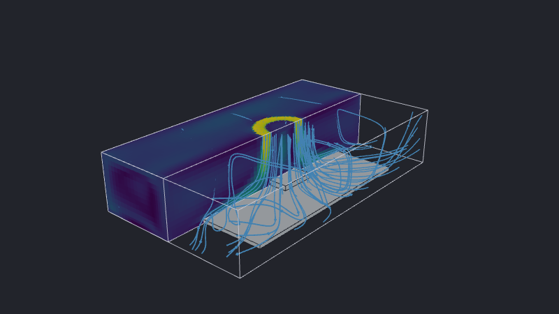
The solved operating point is approximately 0.000502 m³/s at 3.1 Pa, within the supplied fan curve. The fan-curve guide lists the checks to make when an operating point lies near an endpoint.
Open iteration_info.csv and inspect the final rows of junction_temperature_chip:
This preview shows a subset of the rows and columns in iteration_info.csv.
iteration | junction_temperature_chip |
|---|---|
| … | … |
| 247 | 203.1549 |
| 248 | 203.1548 |
| 249 | 203.15395 |
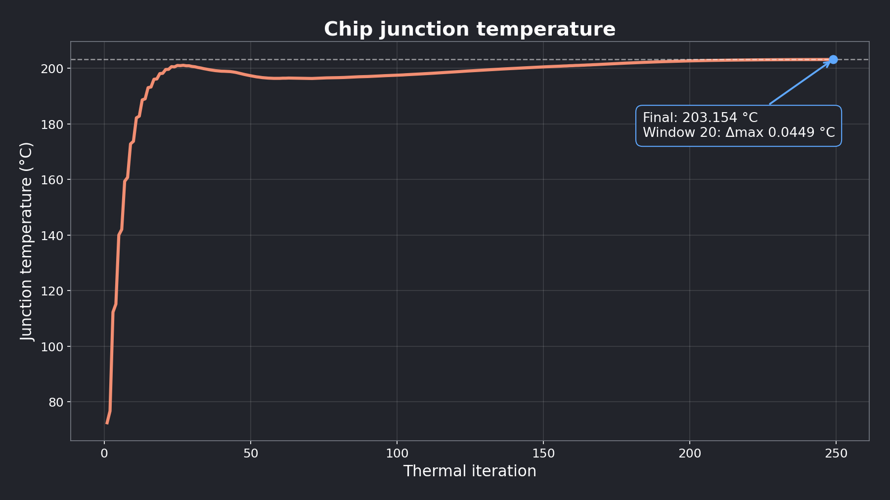
The fan reduces the junction temperature from 254.858 °C in the uniform-inlet result to 203.154 °C: a 51.705 °C improvement, but still 123.154 °C above the goal. The hypothesis was incorrect. Air speed increased, but the small package surface still limits heat transfer.
Select Temperature in the interactive result. Its scale covers the complete 20.0–203.2 °C computed range. Keeping the camera fixed makes the lesson clear: the jet reaches the right place, but the exposed package does not provide enough heat-transfer area.
Convergence means the result has settled, not that the cooling strategy is acceptable. The next page adds a heatsink while keeping this fan setup unchanged.
Airflow change measured
We:
- placed an annular fan inlet above the chip;
- supplied a pressure–flow curve instead of imposing one speed;
- used k–ω SST for the fan-driven flow; and
- measured the improvement in junction temperature.
We tested one change while keeping the chip load and junction model fixed. The temperature fell, so the fan helps; it did not reach 80 °C, so the result points directly to the next intervention. In the next chapter, we will add a CAD heatsink to spread the chip’s heat into the airflow we have just established.