Configure the mesh
Balance mesh detail and cell count by choosing where finer spacing is needed, which geometric features to preserve, and which small details can be simplified. These controls help you capture the geometry that matters for your simulation while avoiding unnecessary cells.
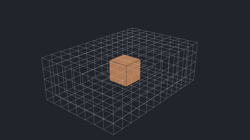
Merge the settings below into your existing request. Each plot compares one setting at a time in the same fluid domain, using cuboids or the CAD tutorial’s heatsink.
Set the global cell size
mesh_settings.max_cell_size sets the global upper limit on cell size, in meters:
{
  "mesh_settings": {
    "max_cell_size": 0.002
  }
}
Use [x, y, z] values to set different limits by direction. A null entry leaves that direction without an explicit upper limit.
Refine a component
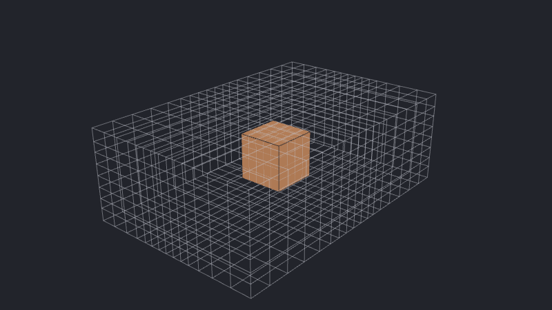
Component max_cell_size sets a local cell-size limit within the component’s bounding box. Add it to either a cuboid component or a CAD component:
{
  "tag": "box",
  "max_cell_size": 0.0005
}
A value smaller than the global limit adds refinement for component features. Because cells grow with finite growth-rates, this also adds refinement to the surrounding region of said component.
Preserve CAD vertices
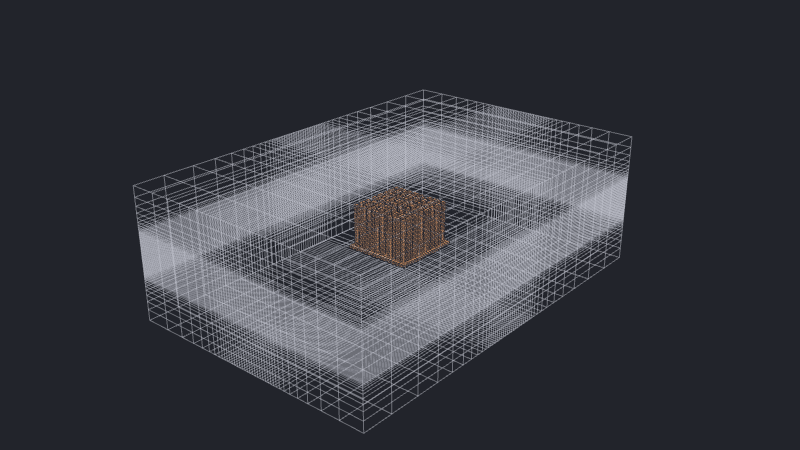
preserve_cad_vertices adds mesh planes at the imported CAD vertices. Set it on a CAD component to align the mesh with features such as pin edges and gaps:
{
  "tag": "pinned_heatsink",
  "preserve_cad_vertices": true
}
This is enabled by default. Turning it off leaves the CAD shape represented by the mesh built from the other sizing controls. Preserving vertices can improve feature alignment, but detailed geometry can introduce many closely spaced planes and increase the cell count.
Merge nearby mesh planes
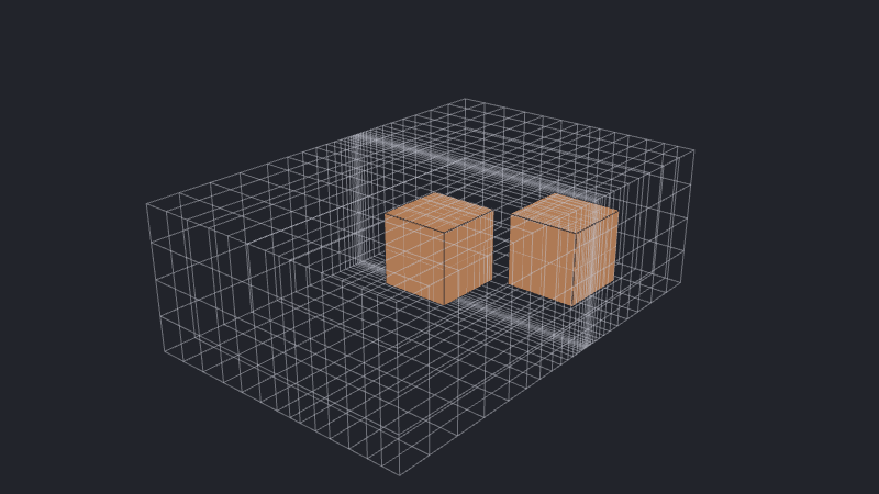
mesh_settings.fuse_threshold merges fixed axis coordinates that are closer than the threshold, in meters. Increase it to remove narrow cell intervals caused by nearly aligned component faces:
{
  "mesh_settings": {
    "fuse_threshold": 0.001
  }
}
Fusing works independently on each axis and can move component faces. In this example, the nearby x coordinates merge while the boxes remain separated along y.
Remove small cuboid components
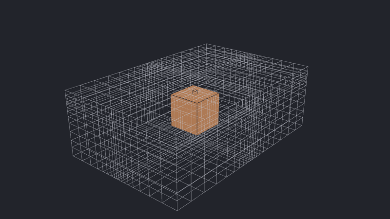
mesh_settings.bbox_cull_threshold removes cuboids whose three dimensions are all below the threshold, in meters. Increase it to omit small components that do not need to be represented:
{
  "mesh_settings": {
    "bbox_cull_threshold": 0.003
  }
}
This removes the component and the fixed mesh planes it contributes. In the example below, a 3 mm threshold removes the 2 mm cube attached to the larger box. This setting does not remove CAD components.
Refine a boundary region
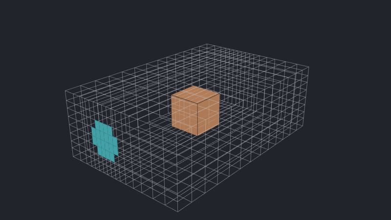
mesh_resolution controls the number of cells across a boundary region. For a circle, it requests at least that many cells across its diameter:
{
  "boundary": {
    "circle": {
      "side": "x_min",
      "center": [0.05, 0.02],
      "radius": 0.01,
      "mesh_resolution": 12
    }
  }
}
Smooth cell-size transitions
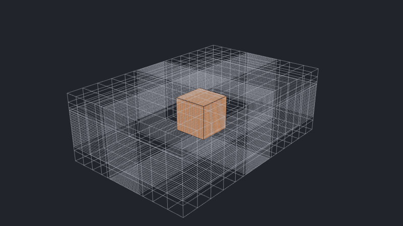
max_growth_rate limits size changes between neighboring cells. boundary_layer_growth_rate controls growth through estimated boundary layers, and max_aspect_ratio limits cell stretching:
"mesh_settings": {
  "max_cell_size": 0.002,
  "max_growth_rate": 1.2,
  "boundary_layer_growth_rate": 1.2,
  "max_aspect_ratio": 30.0
}
Lower growth limits make spacing change more gradually. A lower aspect-ratio limit restricts stretching. Both can increase the total cell count.
See also
- CAD voxelization explains how resolution and vertex preservation affect imported shapes.
- Rectilinear meshing explains how local requirements affect the wider mesh.
- Mesh resolution and controls explains how the mesher combines its constraints.
- Tutorial: Add a CAD heatsink uses vertex preservation to retain the heatsink’s pin geometry.