Add a CAD heatsink
The fan delivered air to the right place, but the 203.154 °C junction showed that the exposed package had too little area to use it. On this page, we will add a pinned STEP heatsink, check its mesh, and test whether spreading the same 6 W load into that airflow reaches the 80 °C goal.
This page is part of Design a complete electronics cooling solution.
Choose how to start:
- Start with annular-fan.json from the previous tutorial. Copy it
and rename the copy
cad-heatsink.json. - Skip the edit on this page and download the completed cad-heatsink.json, then continue with Check the CAD mesh. It contains the STEP data, so it can be submitted by itself.
1. Add the heatsink
The STEP model has a 30 × 30 × 1 mm base and 64 pins, each 2 mm square and 19 mm tall. Its base covers the complete 16 × 16 mm chip and overhangs it evenly:
Download pinned-heatsink.step into the directory containing
cad-heatsink.json. From that directory, encode the STEP file as a single-line base64 value:
# Encode the STEP file and remove line breaks for the JSON string.
base64 < pinned-heatsink.step | tr -d '\n'
Copy the command’s output. Open cad-heatsink.json, add this top-level array, and paste the output
in place of PASTE_BASE64_CONTENTS_HERE:
"cad_components": [
  {
    "tag": "pinned_heatsink",
    "contents_base64": "PASTE_BASE64_CONTENTS_HERE",
    "units": "mm",
    "translation": [0.0485, 0.02, 0.0038],
    "rotation": [0.0, 0.0, 0.0],
    "preserve_cad_vertices": true,
    "max_cell_size": 0.003,
    "thermal_model": {
      "conducting": {
        "conductivity": 205.0,
        "density": 2700.0,
        "specific_heat_capacity": 900.0,
        "power": 0.0
      }
    }
  }
]
The units value converts the STEP coordinates from millimeters, and translation centers its base
on the chip at z = 0.0038 m. The annular fan, k–ω SST model, PCB, and chip remain unchanged from
the preceding case.
Add a CAD component covers the same encoding workflow, along with units, transforms, and thermal representations for another STEP or STL model.
2. Check the CAD mesh
CAD voxelization explains how the STEP surface becomes solid cells and why preserving vertices matters.
First, change:
"preserve_cad_vertices": false
Keep dry_run set to true and submit the request. The left side of the comparison below shows
the resulting heatsink mesh: without the STEP vertex planes, the pins have uneven widths and some do not properly align on the base.
Now, restore:
"preserve_cad_vertices": true
Submit another dry run. From the image below, we can see that preserving the CAD vertices results in a cleaner representation, with all the pins having uniform size and correct placement.
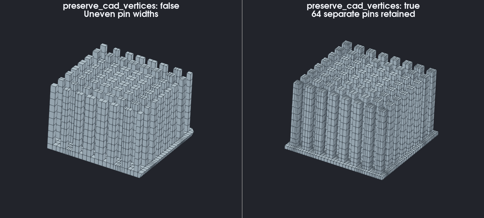
Vertex preservation adds mesh planes at the important STEP vertices. If the pin gaps are still poorly represented, reduce the CAD component’s max_cell_size and repeat the dry run.
3. Run the cooled-chip simulation
Set dry_run to false, submit the request, and download the result. The validated 113,296-cell case stops with monitor_converged after 106 iterations.
Open iteration_info.csv and inspect the final rows of junction_temperature_chip:
This preview shows a subset of the rows and columns in iteration_info.csv.
iteration | junction_temperature_chip |
|---|---|
| … | … |
| 104 | 42.186806 |
| 105 | 42.192635 |
| 106 | 42.19766 |
The heatsink reduces the converged junction temperature from 203.154 °C in the fan-only result to 42.198 °C, comfortably below the 80 °C target for this exercise.
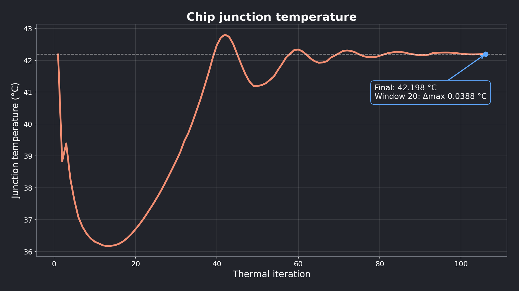
Convergence only means the result has settled. Compare it with the chip manufacturer’s maximum junction temperature before accepting the thermal strategy.
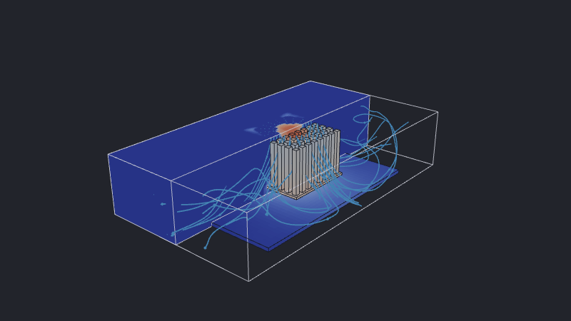
Inspect fluid.vtu and solid.vtu together with a VTU viewer. Look for:
- heat spreading from the chip into the base and pins;
- the annular fan jet entering the gaps between the pins; and
- air leaving toward both ends of the duct.
The interactive result keeps the complete PCB, chip, and heatsink while displaying only the back half of the fluid field. The front half is cut away at the duct center plane; the white box marks the complete solved domain. Blue arrowed streamlines begin at the annular inlet and follow the air through the pin field toward the outlets. Open Display and uncheck Fluid to inspect the complete solid assembly, or Streamlines to hide the airflow paths. Follow the optional ParaView workflow to reproduce that view from the downloaded files.
Design goal reached
We:
- added and positioned an embedded STEP component;
- checked narrow CAD features with a dry run;
- preserved the pin boundaries in the solver mesh; and
- measured the heatsink’s effect on chip junction temperature.
Use Conducting and insulating domains to understand the material behavior and Add a CAD component to adapt another heatsink.
The reward is a defensible design comparison: fan-only cooling settled at 203.154 °C, while the same fan and chip with a meshed heatsink settled at 42.198 °C. We used the result to identify a missing heat-transfer path, added one physical intervention, and passed the 80 °C goal by 37.802 °C.
Next, test a Raspberry Pi 5 at its maximum operating point and transfer the same reasoning to a complete electronics assembly: assess the bare board first, then add active cooling while holding the operating point fixed.