CAD voxelization
Vanellus represents imported CAD as solid cells within the same rectilinear mesh as the surrounding fluid. This process is called voxelization. The resulting solid follows the cell faces, so its detail depends on both mesh spacing and the CAD’s orientation relative to the coordinate axes.
From a surface mesh to solid cells
Vanellus first represents the CAD component as a triangulated surface mesh. For STEP files, it generates triangles from the CAD surfaces; STL files already contain them.
The mesher uses this surface to determine which cells in the shared rectilinear mesh belong to the solid. Together, these cells form the voxelized component, whose boundary follows the axis-aligned cell faces. Mesh spacing therefore determines how closely the final solid represents the imported surface.
Why angled surfaces become steps
An axis-aligned flat surface can coincide with a mesh plane. A curved or oblique surface cannot: the solid–fluid boundary follows a staircase of rectangular cell faces. Finer spacing makes the steps smaller, but does not introduce curved or angled cell faces.
The comparison below uses the tutorial’s pinned heatsink, first aligned with the mesh and then rotated 45° about z. The CAD dimensions, cell-size limits, and fluid domain stay the same, and vertex preservation is enabled in both views. Translation keeps the heatsink centered after rotation.
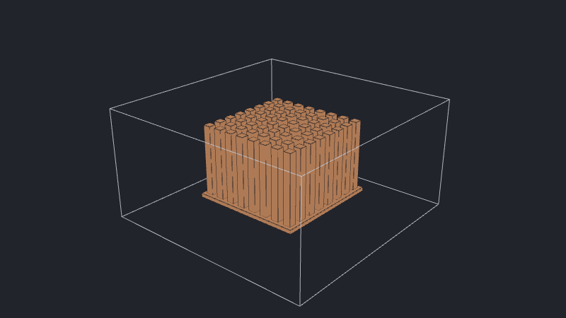
This geometric approximation can change pin widths, passage openings, solid volume, and exposed surface area. Thin walls or narrow gaps may disappear if the mesh does not distinguish their interiors. These changes can affect flow resistance and heat-transfer paths, so the mesh needs to retain the geometry relevant to the modeled problem.
What preserving CAD vertices does
preserve_cad_vertices is enabled by default. It adds fixed mesh coordinates at imported vertex positions after placement: a vertex at [x, y, z] contributes one plane perpendicular to each axis. These planes extend through the domain, rather than ending at the component.
For STEP, the preserved points are the original CAD vertices, not every extra triangle vertex introduced by tessellation. For STL, they are the vertices of the supplied triangle mesh.
Preservation is particularly useful for predominantly cuboidal parts: planes through pin edges and the top and bottom of a thin base can retain their dimensions. It does not rotate mesh planes or trace a curve between vertices. The 45° heatsink above therefore remains stepped even with preservation enabled.
Detailed geometry can contribute many closely spaced coordinates, increasing the cell count throughout the mesh. Nearby coordinates are also subject to fusing. With preservation disabled, classification still uses the same CAD surface, but the mesh no longer receives these vertex coordinates.
Preserve CAD vertices shows how to configure the setting and compares it off and on for the aligned heatsink.
Resolution of the voxelized shape
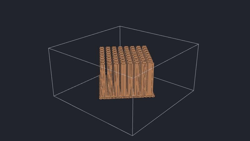
Global and component max_cell_size limits control the spacing available to represent the surface. This comparison keeps the heatsink at 45° and reduces only its x- and y-direction cell-size limits. The z-direction limit and vertex-preservation setting stay unchanged.
See also
- Add a CAD component for importing, rotating, and translating CAD.
- Configure the mesh for interactive examples of cell-size limits and vertex preservation.
- Mesh resolution and controls for how sizing, fixed planes, and fusing interact.
- Tutorial: Add a CAD heatsink for the pinned heatsink used in these comparisons.