Add a CAD component
Add closed STEP or STL geometry to cad_components. Use cuboids instead when a box captures the required shape more clearly and cheaply.
Encode the source file
Create a single-line base64 value for the request:
# Encode the CAD bytes and remove line breaks for the JSON string.
base64 < enclosure.step | tr -d '\n'
Insert the output as contents_base64 and declare the units used by the CAD file:
{
  "tag": "enclosure",
  "contents_base64": "PASTE_BASE64_CONTENTS_HERE",
  "units": "mm",
  "thermal_model": "insulating"
}
Add this object to the top-level cad_components array.
Set units to the units used by the source file. For an unlisted unit, use the custom conversion form documented in the API reference.
Rotate and translate the component
Set rotation to [x, y, z] angles in radians. Vanellus applies these rotations in x, then y, then z order, about the origin of the CAD file’s coordinate system. Set translation to the [x, y, z] offset in meters; this is applied after rotation, along the simulation axes.
Add these fields to your CAD component. Zero values keep the source position and orientation after unit conversion:
{
  "rotation": [0.0, 0.0, 0.0],
  "translation": [0.0, 0.0, 0.0]
}
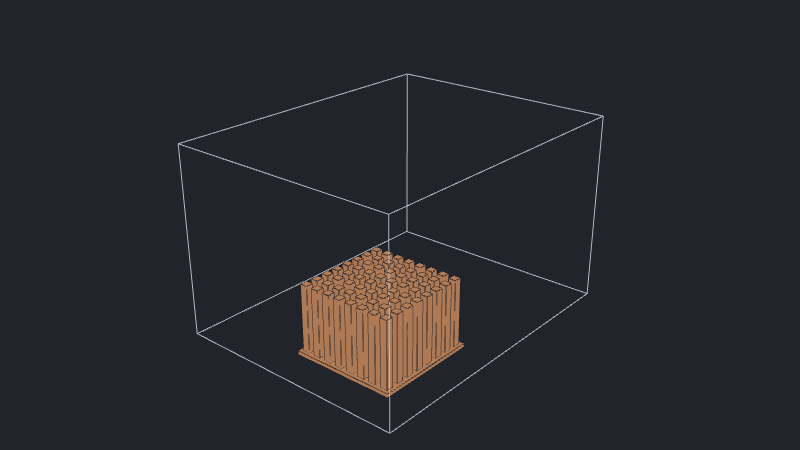
For example, the following rotates a part by 90° about x (1.5707963 radians), then moves it 45 mm along x, 40 mm along y, and 10 mm along z:
{
  "rotation": [1.5707963, 0.0, 0.0],
  "translation": [0.045, 0.04, 0.01]
}
Choose the angles and offsets for your assembly, keeping the transformed part inside the computational domain. The plot illustrates the two placements above using the tutorial’s pinned heatsink.
Choose the thermal representation
Use "insulating" for an excluded, adiabatic solid. Use a conducting model when the part participates in heat transfer:
"thermal_model": {
  "conducting": {
    "conductivity": 205.0,
    "density": 2700.0,
    "specific_heat_capacity": 900.0,
    "power": 0.0
  }
}
CAD components cannot use compact thermal models or carry explicit boundary conditions. Conducting and insulating domains explains the two supported representations.
Align rectangular CAD where possible
Where the model allows it, align the main faces of rectangular CAD with the coordinate axes. At oblique angles, the surfaces become stepped and may need finer spacing to retain the same geometric detail. Alignment can therefore reduce the required cell count. CAD voxelization shows this effect. Preserve the part’s intended orientation relative to the flow, gravity, and neighboring components.
If axis-aligned boxes capture the required geometry, consider building an assembly from cuboids instead, retaining the flow passages and thermal contacts that matter.
See also
- CAD voxelization explains how CAD surfaces become solid cells and why angled faces appear stepped.
- Geometry and the computational domain explains how components displace fluid.
- Mesh resolution and controls explains CAD vertex preservation and its interaction with mesh-plane fusing.
- Preserve CAD vertices compares the heatsink mesh with vertex preservation off and on.
- Configure the mesh shows how to refine components and nearby clearances.
- Tutorial: Add a CAD heatsink uses a CAD component in a complete electronics cooling simulation.